
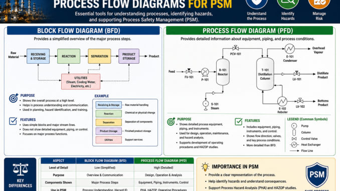
A PSM block flow diagram or simplified process flow diagram provides a visual overview of the covered process and its major streams. Under 29 CFR 1910.119(d)(2)(i)(B), process-technology information must include a block flow diagram or simplified process flow diagram. OSHA’s Appendix B supplies nonmandatory examples.
Appendix B is nonmandatory, but the underlying PSI requirement is mandatory. A facility can use its own drawing standard as long as the process-technology information required by paragraph (d) is complete, accurate, and suitable for the people using it.
What OSHA Appendix B contains
Appendix B presents two examples:
- An example block flow diagram showing major process operations and streams; and
- An example simplified process flow diagram showing more equipment and flow detail.
These examples illustrate possible formats. They do not establish one required symbol set, sheet size, level of detail, or software platform. The appropriate diagram should communicate the covered process clearly and remain consistent with the actual process.
PSM Block Flow Diagram versus PFD versus P&ID
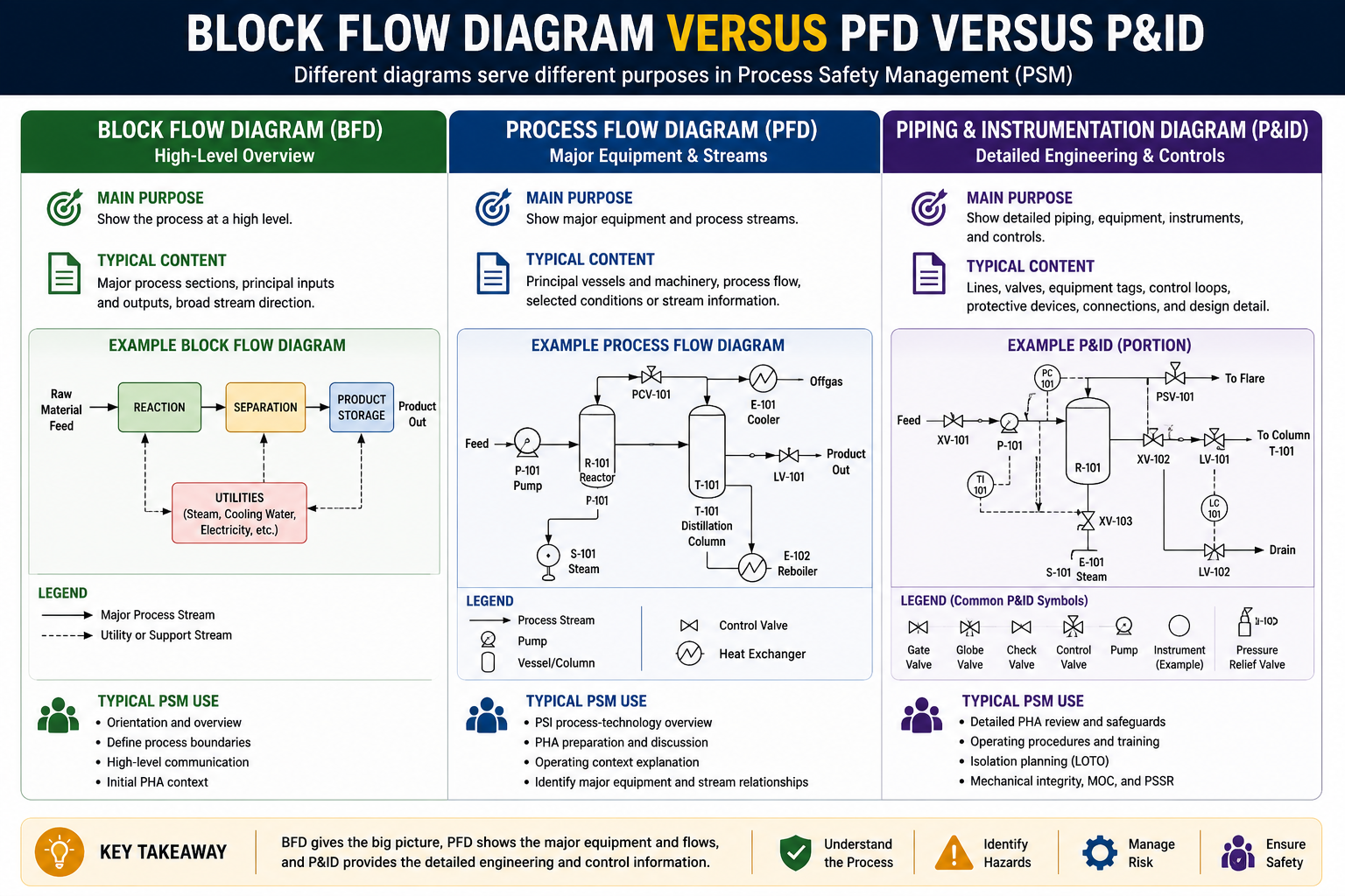
| Document | Main purpose | Typical content | Typical PSM use |
|---|---|---|---|
| Block flow diagram (BFD) | Show the process at a high level. | Major process sections, principal inputs and outputs, broad stream direction. | Orientation, process boundary discussion, initial PHA context. |
| Simplified process flow diagram (PFD) | Show major equipment and process streams. | Principal vessels and machinery, process flow, selected conditions or stream information. | PSI process-technology overview, PHA preparation, operating-context explanation. |
| Piping and instrumentation diagram (P&ID) | Show detailed piping, equipment, instruments, and controls. | Lines, valves, equipment tags, control loops, protective devices, connections, and design detail. | Detailed PHA review, procedures, isolation planning, mechanical integrity, MOC, and PSSR. |
These categories can overlap because company drafting standards differ. Define the intended content of each document in the site’s drawing procedure instead of relying on the title alone.
Process-technology information required with the diagram
The diagram is one part of the information required by 1910.119(d)(2). Process-technology PSI must include at least:
- Process chemistry;
- A block flow diagram or simplified process flow diagram;
- Maximum intended inventory;
- Safe upper and lower limits for temperature, pressure, flows, or composition; and
- An evaluation of the consequences of deviations, including those affecting employee safety and health.
Where original technical information no longer exists, OSHA requires it to be developed with the process hazard analysis in sufficient detail to support that analysis.
What a useful block flow diagram should communicate
A BFD should allow a knowledgeable reader to identify the major process sequence without being buried in piping detail. Depending on the process, it may show:
- Raw-material feeds and product, by-product, recycle, purge, waste, and utility streams;
- Major reaction, separation, storage, treatment, compression, heating, or cooling sections;
- Direction of principal flow;
- Interfaces with upstream, downstream, and shared systems;
- Covered-process boundaries and connected inventories; and
- Major release or disposal destinations where needed for understanding.
A block diagram should remain readable when printed or viewed at normal size. If every valve and instrument is included, it has stopped serving as a high-level orientation PSM Block Flow Diagram tool.
What a simplified process flow diagram should communicate
A simplified PFD usually adds major equipment and stream relationships. It may identify equipment tags, principal process conditions, important recycles, utility exchanges, relief destinations, or major control functions when those details help explain the technology.
Do not assume the PFD contains every detail needed for hazard analysis. The PHA team may also need P&IDs, equipment specifications, relief-system design, electrical classification, interlock descriptions, cause-and-effect information, materials of construction, ventilation PSM Block Flow Diagram design, and other process safety information.
Use diagrams to define the covered process
The PSM definition of “process” includes activities involving highly hazardous chemicals, including use, storage, manufacturing, handling, or on-site movement, and treats interconnected vessels as one process. Separate vessels can also be considered a single process when located so that a highly hazardous chemical could be involved in a potential release.
A diagram can support the boundary analysis by showing interconnections, proximity, shared equipment, transfer paths, and inventories. The drawing itself does not decide legal coverage, but an incomplete boundary can cause PSI, PHA, procedures, and mechanical-integrity scope to omit PSM Block Flow Diagram connected hazards.
Validate diagrams against the field
Before relying on a diagram, compare it with current field conditions and supporting records. A validation walkdown can examine:
- Equipment identity and service;
- Major connections and flow direction;
- Temporary hoses, bypasses, jumpers, or portable equipment;
- Disconnected or abandoned equipment;
- Relief and vent destinations;
- Shared utilities and safeguards;
- Changes awaiting as-built updates; and
- Consistency among BFDs, PFDs, P&IDs, procedures, and equipment records.
Record discrepancies, assess whether they affect current risk, and correct PSM Block Flow Diagram them through the appropriate document-control and management-of-change process.
Document control through the process lifecycle
Assign every controlled diagram a document number, title, process or unit, revision, approval, and effective date. Define who may edit it, how field markups are reviewed, when an as-built update is due, and how superseded versions are removed or archived.
Changes affecting a diagram may also affect PSI, procedures, training, mechanical-integrity scope, the PHA, and PSSR. During MOC closeout, verify that revised diagrams match the approved installed condition. During a pre-startup safety review, unresolved drawing differences should be evaluated against the required design, procedure, hazard-analysis, and training PSM Block Flow Diagram confirmations.
Common process-diagram weaknesses
- Using a detailed P&ID as the only orientation diagram;
- Drawing process blocks without identifying major streams or direction;
- Leaving connected or proximate equipment outside the documented process boundary;
- Using obsolete tags or equipment service descriptions;
- Failing to show important recycle, purge, waste, vent, or utility relationships;
- Allowing temporary modifications to remain undocumented;
- Treating an Appendix B example as a mandatory drawing template; and
- Updating a PFD while leaving related P&IDs, PSI, procedures, PSM Block Flow Diagram or training inconsistent.
Diagram readiness checklist
- Is the drawing purpose and level of detail defined?
- Are major equipment, inputs, outputs, recycles, and interfaces understandable?
- Does the documented boundary reflect interconnection and proximity?
- Can the diagram support process orientation and PHA preparation?
- Does it agree with current field conditions and other controlled drawings?
- Are revision, approval, and as-built responsibilities clear?
- Are discrepancies controlled through MOC and PSM Block Flow Diagram corrective-action systems?
Related PSM requirements
Related Guides
- OSHA1926.65: Emergency Response at Hazardous Sites
- Who Is Responsible for Scaffold Safety Under OSHA Regulations?
- Hazard Identification & Risk Assessment (HIRA) for Rebar Fixing & Assembly Work
- PSM Part 1 – Comprehensive Guide to OSHA 3132 Process Safety Management
- OSHA Housekeeping: Workplace Compliance


Be the first to comment