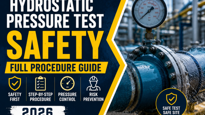
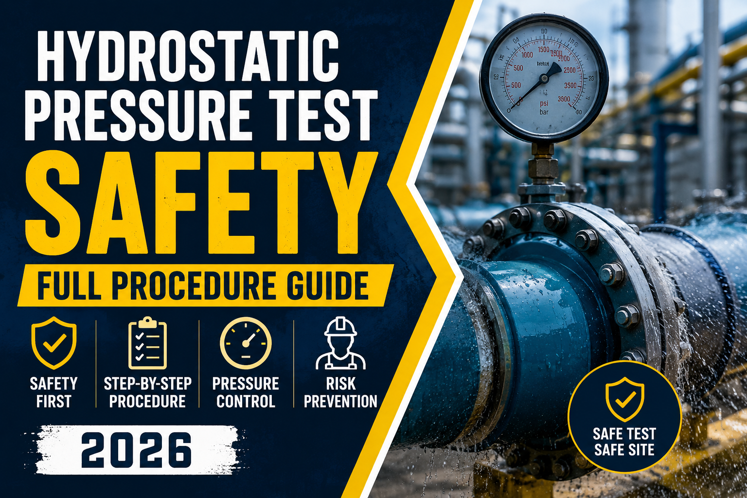
Hydrostatic pressure test safety rests on four controls: preventing structural overload from the weight of test liquid, locking down site access around the pressurized system, purging trapped air before pressurization, and controlling the rate of pressure rise. Get these four wrong and you get either a structural collapse, a struck-by injury, an inaccurate test, or – in the worst case – a violent failure. This guide walks through each control the way an interviewer for a Saudi Aramco or major EPC contractor safety role will expect you to explain it. If you’re building out a broader interview prep plan, pair this with our safety officer test preparation guide – plus you’ll find a checklist, FAQ, and links to the primary references below.
Purpose. This procedure exists to protect personnel, equipment, and the asset itself during hydrostatic and pneumatic pressure test operations on piping, vessels, and pipelines. It applies from the moment a test package is issued through final depressurization and drain-down. It is written to align with the intent of OSHA’s General Duty Clause (29 U.S.C. §654(a)(1)), the federal pipeline safety regulations at 49 CFR Parts 192 and 195, and the testing provisions of ASME B31.3 and ASME PCC-2. Where a project specification, client standard, or local regulator sets a stricter requirement, that stricter requirement governs. If you’re specifically prepping for a Saudi Aramco safety officer interview, our Aramco safety officer test preparation guide breaks down the exact rules assessors probe on this topic.
1. Prevention of Overload from Weight of Liquid
This chapter covers combining hydrostatic and pneumatic test methods correctly, installing temporary supports before filling, and consulting the engineering department before any test begins.
A pipe designed to carry gas or a light product was never sized to carry a column of water. Water weighs roughly 1,000 kg per cubic meter – fill a large-bore line or a tall vessel with it and you’ve added a load the original supports may not have been designed to carry. That’s the overload risk, and it’s the first thing a competent safety officer checks before signing off a test pack.
Combining hydrostatic and pneumatic methods.
- Hydrostatic testing (water or another test liquid) is the default method because liquid is essentially incompressible – if a failure occurs, the stored energy release is comparatively small.
- Pneumatic pressure test methods use compressed gas, which is compressible and stores far more energy. A rupture during a pneumatic test can throw fragments like shrapnel. Pneumatic testing is only used when hydrostatic testing isn’t practical – for example, when the system can’t tolerate moisture, when ambient temperature risks freezing the test liquid, or when the structure can’t support the added liquid weight.
- A hydrostatic-pneumatic (mixed) test may be used to reduce liquid weight while still limiting stored energy; if that route is chosen, the gas-filled portion must be treated under pneumatic test rules for exclusion zones and pressurization steps.
Temporary supports.
- Before filling, verify that pipe racks, saddles, hangers, and vessel foundations can carry the filled weight, not just the empty weight.
- Install temporary supports, shoring, or additional bracing wherever the engineering review flags a gap – sleepers under elevated spool sections, extra dunnage under skids, or blocking under vessel skirts.
- Check that temporary supports themselves sit on stable, load-bearing ground. A temporary support on soft or uneven ground is not a support.
Consult engineering before testing.
- Never fill a system for test without a signed-off test pack that has been reviewed by a piping or structural engineer.
- The engineering review should confirm: test medium, test pressure, support adequacy under filled weight, and any elevation-related pressure effects (static head) that change the effective test pressure at high and low points.
- If field conditions differ from the test pack (different supports installed, different fill sequence, different ambient temperature), stop and get the engineer to re-confirm before proceeding.
2. Site Access Control
This chapter covers barricading the test area, posting warning signage, positioning personnel away from hazard zones, and where pump operators should stand during pressurization.
Pressure testing is a prevention of overload and exclusion-zone problem before it’s anything else, and the logic mirrors what’s covered in our confined space entry guide for controlling exactly who’s inside a hazard zone and when. Most pressure-test injuries happen because someone was standing where they shouldn’t have been when something let go – a fitting, a temporary blank, a gauge connection.
Barricading.
- Establish a barricaded exclusion zone around the entire test boundary before pressurization starts, not after.
- Use hard barriers or barrier tape plus physical stanchions on all approach routes, including from above (scaffolding, elevated walkways) and below (pits, trenches).
- Extend the barricade further for pneumatic or hydrostatic-pneumatic tests than for a straight hydrostatic test, given the higher stored-energy risk.
Warning signage.
- Post “Pressure Test in Progress – No Entry” signage at every access point to the barricaded area.
- Signage should state the hazard (pressure test), the status (in progress / holding / depressurizing), and who to contact.
- Signage stays up until the system is confirmed fully depressurized and drained – not removed the moment the gauge reads zero.
Personnel posting and access limits.
- Limit personnel inside the barricade to only those directly required to run the test.
- Post a dedicated person at each access point during pressurization and hold periods to stop unauthorized entry – this is not optional on a live test.
- No one approaches gauges, connections, or fittings while the system is under pressure. Readings are taken from outside the exclusion zone or via remote gauges/transmitters wherever practical.
Pump operator positioning.
- The pump or compressor operator should be stationed away from the direct line of fire of the piping or vessel being tested – not directly in front of flanges, blind flanges, or temporary test heads.
- Position the pump so the operator can see the gauge and hear/receive the stop instruction without standing beside pressurized fittings.
- A second person should monitor the test boundary and communicate directly with the pump operator so pressurization can be stopped immediately if anyone reports an anomaly.
3. Air Removal
This chapter covers venting at high points while filling from the low point, and using scrapers or pigs to displace air in long pipeline runs.
Trapped air is both a safety hazard and a data-quality problem – the same fill-low, vent-high logic covered in our dewatering safety guide applies here, since removing unwanted air is really the mirror image of removing unwanted water. Air is compressible; a pocket of trapped air inside an otherwise liquid-filled system behaves like a small pneumatic test hidden inside your hydrostatic test, and it will also throw off your pressure readings and volume calculations.
Fill low, vent high.
- Always fill from the lowest point of the system and open vents at every high point before starting to fill.
- Keep high-point vents open until liquid discharges freely with no visible bubbles – that’s the sign the air pocket at that point is gone.
- Close each vent only after confirming a solid liquid stream, then move to the next.
- Close all vents before pressurization begins; an open vent during pressurization defeats the test and creates a jet hazard.
Scrapers and pigs for pipeline runs.
- On long pipeline sections, use scrapers (pigs) ahead of the fill water to physically displace air out of the line rather than relying on venting alone.
- Track scraper position where practical so operators know where the air/water interface is in the line.
- Coordinate scraper launch and receipt with the same access-control measures used for the rest of the test – a stuck or fast-moving scraper is itself a hazard.
Why it matters for the test result.
- Residual air compresses under pressure and can mask a small leak – the system may appear to hold pressure while air, not lack of leakage, is absorbing the pressure drop.
- Complete air removal is a prerequisite for a valid hydrostatic test record, not just a safety nicety.
4. Pressure Rise Control
This chapter covers the general principle of raising pressure gradually and in a controlled, monitored manner rather than any single fixed rate or step schedule.
Pressure should never be brought up quickly, and it should never be brought up unattended. The exact staging, hold points, and rates for a given job are set out in the applicable code and the project’s specific test procedure – they vary by system, test medium, and hazard classification, so this section deliberately doesn’t prescribe numbers. What’s constant across every job is the qualitative approach.
General principles.
- Increase pressure gradually and in stages rather than in one continuous ramp to atmospheric-to-test-pressure.
- Pause at defined intermediate hold points to let the system stabilize and to allow a visual and instrument check before continuing.
- Monitor gauges continuously during pressurization – someone should be watching the reading the entire time pressure is rising, not just at the end.
- Stop immediately and investigate any unexpected pressure drop, unusual noise, visible movement, or leakage – don’t “wait and see” whether it resolves on its own.
- Never exceed the test pressure specified in the approved test pack, and never rely solely on the pump’s own gauge if an independent calibrated gauge is specified for the record.
- Depressurization at the end of the test follows the same logic in reverse: controlled, gradual release from a high point, never a sudden opening of a valve or fitting under pressure.
Why generic guidance here is the right call.
- Ramp rates, hold-point pressures, and step counts are defined by the specific code edition, the system’s hazard category, and the client specification in force for that job.
- Quoting a fixed number without confirming which code edition and hazard class applies is a common interview mistake – the safer, defensible answer is to describe the method (gradual, staged, monitored, with defined stops) and state that exact figures come from the approved test procedure for that specific job.
Practical Checklist
Before filling:
- Test pack reviewed and signed off by engineering
- Support adequacy checked for filled (not empty) weight
- Temporary supports installed and inspected
- Test method confirmed (hydrostatic / pneumatic / mixed) and justified if pneumatic
- Barricades and signage erected around full test boundary
- Access points staffed or controlled
During fill and air removal:
- Filling from lowest point confirmed
- All high-point vents open before fill starts
- Vents closed only after bubble-free flow confirmed
- Scraper/pig run coordinated on long pipeline sections
During pressurization:
- Pump operator positioned out of the line of fire
- Gauges monitored continuously
- Pressure raised gradually with defined hold points
- Anomalies (drop, noise, movement, leak) trigger immediate stop
At completion:
- Controlled, gradual depressurization from a high point
- Signage and barricades remain until system confirmed fully depressurized and drained
- Test record completed and filed
FAQ
What’s the main difference between hydrostatic and a pneumatic pressure test in terms of risk? Hydrostatic testing uses liquid, which is essentially incompressible, so if something fails the stored energy released is comparatively limited. A pneumatic pressure test uses compressed gas, which is compressible and stores much more energy – a failure can release that energy violently and throw fragments. That’s why pneumatic testing is only used when hydrostatic testing isn’t practical.
How do you prevent overload from the weight of test liquid? Confirm with engineering that existing supports were designed for, or have been checked against, the filled weight of the system – not just the empty weight. Install temporary supports wherever that check shows a shortfall, and never proceed with filling until engineering has signed off the test pack.
Why is air removal treated as a safety issue, not just a quality issue? Trapped air is compressible. Under pressure it can mask a real leak (the system seems to hold pressure while the air pocket is compressing) and it adds an unplanned stored-energy element to what’s supposed to be a low-energy hydrostatic test. Filling from the low point and venting at every high point until flow is bubble-free removes that risk.
What is pressure test overload prevention, in plain terms? It’s the combined set of controls – structural support checks, engineering sign-off, controlled/gradual pressurization, and continuous monitoring – that stop a test from exceeding what the system, its supports, or its connections can safely handle. It covers both structural overload (weight of liquid) and pressure overload (exceeding safe test pressure or raising pressure too fast to react to a problem).
Where should the pump operator stand during a hydrostatic test? Away from the direct line of fire of flanges, blind flanges, temporary test heads, or any fitting that could become a projectile if it failed – with a clear view of the gauge and a direct communication line to the person monitoring the exclusion zone.
Do OSHA regulations specify exact test pressures or ramp rates? No single OSHA standard sets numeric hydrostatic test parameters – OSHA’s authority here mainly comes through the General Duty Clause, while the actual test pressures and procedures come from pipeline safety regulations (49 CFR 192/195) and engineering codes such as ASME B31.3 and ASME PCC-2, plus the project’s own approved test procedure. Always confirm figures against the current code edition and job-specific spec rather than quoting a number from memory.
Useful sources
- OSHA Safety and Health Information Bulletin – Pipeline De-Watering (SHIB 06-21-2004)
- OSHA General Duty Clause – Section 5(a)(1), OSH Act
- 49 CFR Part 192 – Transportation of Natural and Other Gas by Pipeline (eCFR)
- 49 CFR Part 195 – Transportation of Hazardous Liquids by Pipeline (eCFR)
- ASME B31.3 – Process Piping (official code page)
- ASME PCC-2 – Repair of Pressure Equipment and Piping (official code page)

1 Trackback / Pingback