
Introduction
Water ingress represents the most pervasive threat to the structural integrity of modern civil engineering projects. When moisture penetrates a building envelope, it initiates a devastating chain reaction. The water travels through the microscopic capillary tracts of porous concrete, carrying dissolved chlorides and sulfates from the surrounding soil directly to the embedded steel reinforcement. This causes the steel to oxidize, expand, and spall the surrounding concrete, severely compromising the load-bearing capacity of the structure. A meticulously crafted waterproofing method statement is the primary defense against this structural degradation.
The analysis provided in this report is derived from technical documentation for major infrastructure projects (such as HVDC Converter Stations) and bridges theoretical documentation with practical site execution. This comprehensive guide integrates deep research on material science, international safety standards, quality control methodologies, and forensic failure analysis to deliver an authoritative blueprint for executing flawless waterproofing works.
What is Waterproofing Works?
Waterproofing works encompass the systematic preparation, application, and protection of impervious chemical or physical barriers designed to prevent water from entering or escaping a structure. Buildings are subjected to relentless moisture loads from precipitation, rising groundwater, lateral hydrostatic pressure against basement walls, and internal vapor condensation.
Concrete is inherently porous, comprised of a network of voids and micro-cracks formed during the hydration and curing process. Without a robust waterproofing membrane, water will inevitably exploit these pathways. Waterproofing works neutralize this threat by encapsulating the structure in a continuous, flexible, and impermeable shield capable of bridging minor structural cracks and withstanding decades of exposure to aggressive groundwater.
Why Waterproofing Fails in Real Projects (IMPORTANT)
Despite the existence of detailed method statements, waterproofing failures remain a leading cause of construction litigation. Forensic engineering investigations demonstrate that membranes rarely fail due to inherent manufacturing defects. Instead, failures originate from poor design detailing, inadequate site preparation, and careless installation practices by allied trades.
-
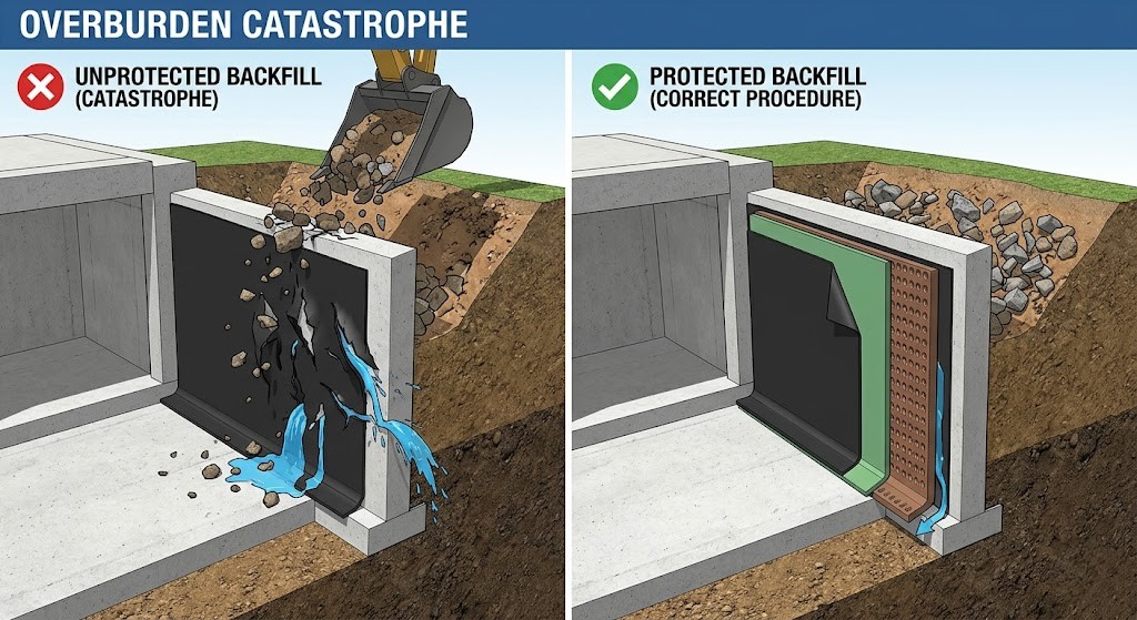
The “Overburden” Catastrophe: Overburden refers to the heavy materials layered over the waterproofing membrane, such as backfilled soil, concrete screeds, or heavy mechanical equipment. When membranes are left unprotected, pouring concrete directly onto the membrane or dragging heavy tools across it causes microscopic punctures. Because the membrane is subsequently buried, these punctures remain hidden until the structure floods.
-
Structural Movement: Buildings settle, expand, and contract. If a rigid waterproofing material is applied across a dynamic joint without proper reinforcement, the movement will snap the waterproofing layer.
-
Defective Terminations: If a membrane simply ends on a vertical wall without a mechanically fastened termination bar and polyurethane sealant, rainwater will run down the facade and slip directly behind the waterproofing.
Purpose of Waterproofing
The execution of these works serves several critical functions:
-
Preservation of Structural Integrity: Stops oxidation by preventing water from reaching the rebar, maintaining the tensile strength of the reinforced concrete.
-
Asset and Interior Protection: Prevents the destruction of expensive interior finishes, electrical conduits, and sensitive mechanical equipment.
-
Occupant Health and Safety: Eliminates chronic moisture intrusion, preventing toxic mold and mildew that degrade indoor air quality.
-
Lifecycle Value Retention: Ensures the building achieves its designed service life without the need for astronomically expensive mid-lifecycle structural remediation.
Tools and Equipment
The successful execution of waterproofing works requires specialized equipment.
| Equipment Category | Specific Tools Required | Primary Function on Site |
| Surface Preparation | Concrete scarifiers, wire brushes, abrasive blast cleaning systems. | To remove cement laitance, loose debris, and curing compounds to achieve an open-textured concrete surface. |
| Bituminous Application | Gas cylinders (100-lb propane), single or double-headed roofing torches. | To heat the modified bitumen membrane to its melting point, allowing it to fuse with the primed substrate. |
| Synthetic Application | Hot air guns, automatic hot-air welding machines, heavy-duty seam rollers. | To weld overlapping seams of PVC or TPO membranes, creating a continuous monolithic layer without open flames. |
| Quality Control & Testing | Leveling instruments, moisture meters, infrared thermometers. | To verify slopes, ensure concrete humidity is below 4%, and monitor surface temperatures. |
Roles and Responsibilities
The execution of a method statement requires a strict chain of command to ensure quality and safety compliance.
| Role | Primary Responsibilities |
| Project/Construction Manager | Oversees the overall implementation and monitoring of all activities detailed in the method statement. |
| Site Manager | Responsible for the overall direction, continuous monitoring, and strict coordination of construction activities. |
| Site Engineer | Directly involved in planning and executing. Prepares shop drawings, formulates safety plans, and arranges work permits. |
| QA/QC Engineer | Conducts rigorous inspections and testing in accordance with the approved Inspection and Test Plan (ITP) and IFC drawings. |
| Foreman | Exercises direct control over working personnel, ensures proper PPE usage, and maintains good housekeeping. |
| HSE Engineer/Supervisor | Reviews Safe Work Plans and permits, and strictly monitors safety compliance during all hot work and lifting activities. |
Step-by-Step Waterproofing Procedure
Phase 1: Surface Preparation and Inspection
-
The 28-Day Cure: New concrete must cure for at least 28 days to allow excess moisture vapor to escape. Applying an impermeable membrane over “green” concrete traps this moisture, causing massive hydrostatic pressure build-up and membrane blistering.
-
Grinding and Smoothing: The surface must be even and perfectly smooth. Sharp projections must be knocked down, and depressions filled with high-strength, non-shrink repair mortar.
Phase 2: Water Proofing Below Grade Level (Tanking System)
-
Primer Application: Apply an approved bituminous primer over the lean concrete. Allow it to cure for a minimum of 6 hours.
-
Membrane Torching & Overlaps: Fix the bituminous insulation membrane using a torch welding technique. Ensure a strict 100mm overlap between adjacent sheets.
-
The Protection Screed: Pour a 50mm protection screed over the horizontal membrane before raft foundation construction begins. This prevents steel fixers from shredding the delicate membrane.
-
Angle Fillets: Construct a 50x50mm sand and cement mortar strip (cant strip) at the intersections of horizontal and vertical surfaces to prevent the membrane from snapping at a 90-degree angle.
-
Vertical Protection: After extending the membrane up the basement walls, fix a 15mm thick protection board to protect the tanking system from the impact of soil backfilling.
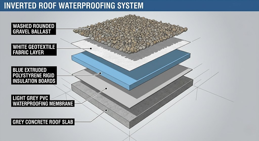
Phase 3: Roof Water Proofing System (Inverted Roof Design)
-
PVC Membrane: Loosely lay a 1.5mm thick PVC membrane across the roof slab. Weld the joints using a specialized hot air gun.
-
Vertical Upstands: Fix the PVC membrane mechanically or with adhesive to parapet walls, terminating it properly at a pre-cut concrete groove.
-
Overburden Layers: Install a separation layer of polyethylene film (200 microns), followed by 100mm extruded polystyrene rigid thermal insulation, a Geotextile fabric layer, and finally 50mm of washed rounded gravel as ballast.
Phase 4: Walkway and Flashing Installation
-
Provide an 800mm wide walkway using loose-laid precast concrete tiles.
-
Fix an aluminum flashing (50mm x 1mm thick) with expansion bolts to the top of the parapet to cover the membrane edge, sealed with UV-resistant sealant.
Types of Waterproofing Systems
Site engineers must understand the broader spectrum of available systems:
-
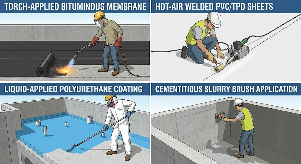
Bituminous Membranes (APP and SBS): Robust, thick, and highly resistant to punctures. Ideal for below-grade work, but labor-intensive and pose fire hazards during application.
-
Synthetic Single-Ply (PVC, TPO, EPDM): Lightweight and highly flexible. PVC offers excellent chemical resistance, TPO reflects heat, and EPDM provides supreme longevity in freeze-thaw climates.
-
Liquid-Applied (Polyurethane): Seamless, monolithic coatings ideal for complex geometries like balconies. Highly sensitive to substrate moisture.
-
Cementitious Waterproofing: A rigid slurry coat best suited for rigid, below-grade structures like water tanks and elevator pits. Lacks elasticity.
Safety Precautions (EHS FOCUSED)
-
Fall Protection (OSHA 1926 Subpart M): Erect highly visible warning lines no less than 6 feet (1.8 meters) from unprotected roof edges. Secure all floor holes and skylights with load-bearing covers.
-
Fire Safety (CERTA): Keep a minimum of two 4A60BC fire extinguishers within 10 feet of active torching. Execute a mandatory two-hour fire watch after all torches are shut down to check for hidden smoldering.
-
Chemical and Gas Hazards: Propane gas is heavier than air and will pool in deep trenches, creating asphyxiation and explosion risks. Ensure forced mechanical ventilation in confined spaces.
Common Mistakes (REAL SITE ERRORS)
-
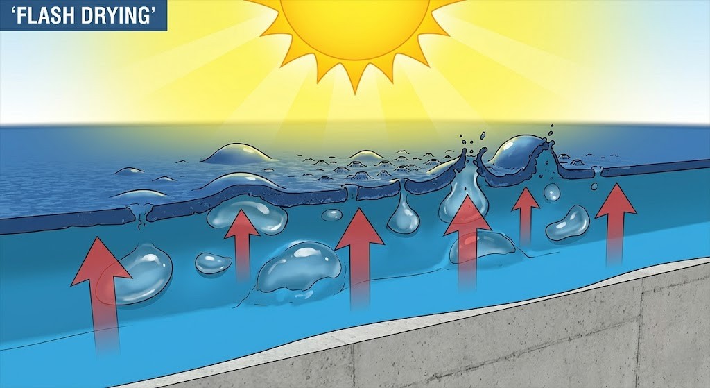
Flash Drying: Applying liquid coatings in peak heat (e.g., 40°C+). The surface skins over instantly, trapping boiling air bubbles that burst and leave thousands of pinholes. Always apply in the early morning.
-
Dew Point Ignorance: Applying polyurethane on humid mornings without checking if the substrate is at least 3°C above the dew point, leading to total membrane debonding.
-
Neglecting Drainage Outlets: Failing to heavily reinforce roof drainage outlets (nallis) and 90-degree parapet junctions with polymer-modified meshes.
Inspection & Quality Control (QA/QC + ITP)

-
The “Bleed-Out” Check: For torched bitumen, the inspector must continuously verify a 3 to 6 mm (1/8 to 3/8 inches) continuous bead of molten asphalt squeezing out along every lap. This proves optimal fusion.
-
The 48-Hour Flood Test: Plug all drains and flood the area with 50mm of water for 24 to 48 hours. If the ceiling slab below shows even the slightest dampness, drain the water, patch the defect, and restart the clock from zero.
Real-Life Failure Scenario (VERY IMPORTANT)
The Case: A commercial building’s boiler room flooded. The contractor blamed “snails eating the sealant.”
The Reality: Forensic engineers discovered the contractor omitted the foam backer rod in the expansion joints. The thin sealant tore during normal daily thermal expansion. Worse, the below-grade sheet membrane had been shredded because the contractor backfilled rocky clay soil without installing a dimpled drainage board. Hydrostatic pressure pushed groundwater through the rips.
The Lesson: Never skip protection boards or backer rods.
Environmental & Weather Considerations
-
Toxicity: Degrading bitumen can leach petroleum byproducts into the soil. PVC undergoes dehydrochlorination, releasing chemical plasticizers into rainwater runoff.
-
Urban Heat Island Effect: Black EPDM or modified bitumen absorbs immense solar radiation. Transitioning to highly reflective white TPO mitigates this impact, reflecting up to 90% of solar heat and reducing building cooling loads.
👷♂️ Pro Tips from Site Engineers
-
Never Trust the Rain App: A sudden rain shower will instantly crater a freshly applied polyurethane coating. If the sky looks threatening, do not start applying.
-
The 16-Hour Tape Test: If a moisture meter is unavailable, tape a 2×2 foot square of clear plastic tightly to the concrete. Leave it overnight. If condensation appears underneath, the slab is too wet to prime.
-
Over-Specify the Backer Rod: Always ensure foam backer rods are 25% wider than the joint opening so they compress tightly and provide a firm base for the caulking.
Quick Checklist for QA/QC
| Verification Item | Acceptance Criteria |
| Concrete Curing | Substrate has cured for a minimum of 28 days. |
| Moisture Content | Concrete humidity is rigorously verified to be below 4%. |
| Corner Detailing | All 90-degree internal corners possess a 50x50mm cant strip. |
| Primer Curing | Applied primer is completely tack-free and dust-free. |
| Torch Bleed-Out | A continuous 3 to 6 mm bleed-out is visible on all seams. |
| Terminations | Aluminum termination bars are mechanically fastened and sealed. |
| Fire Safety | Extinguishers are within 10 feet; a 2-hour fire watch is scheduled. |
| Flood Testing | 48-hour flood test passed with absolute zero moisture detection. |
Conclusion
The successful execution of waterproofing works is an unforgiving engineering discipline. The extracted method statement provides the operational framework, but actual watertight integrity relies on relentless site supervision, unwavering adherence to quality control hold points, and a deep understanding of material physics. By enforcing the 28-day curing rule, executing 48-hour flood tests, and prioritizing worker safety, engineering teams can guarantee the longevity of the assets they construct.
FAQ
1. Why does concrete require a 28-day curing period before applying waterproofing?
During initial hydration, concrete holds massive amounts of internal water. If a membrane is applied too early, escaping moisture vapor becomes trapped, expanding under heat and physically ripping the membrane away from the concrete (blistering).
2. What is the significance of the “bleed-out” in torch-applied bituminous membranes?
The bleed-out is a continuous 3 to 6 mm bead of molten asphalt that squeezes out from overlapping edges. It is the visual proof that the applicator applied enough heat to fuse the sheets without destroying the fiberglass reinforcement.
3. What is “flash drying,” and how does extreme heat destroy liquid membranes?
Flash drying occurs when liquid coatings are applied to concrete exceeding 50°C. The top surface instantly hardens, trapping boiling wet liquid and air beneath it. The air bursts through the surface, leaving thousands of pinholes.
4. Why is a backer rod required when sealing joints with polyurethane caulking?
A foam backer rod prevents “three-sided adhesion,” allowing the sealant to stretch. It also provides structural support, shaping the sealant into an hourglass profile so thermal expansion doesn’t tear it apart.
5. How long must a fire watch be maintained after torch-applied roofing is completed?
In accordance with NRCA CERTA guidelines, a mandatory minimum two-hour fire watch must be executed immediately after torches are extinguished to ensure hidden smoldering in cracks does not escalate into a structural fire.
Be the first to comment