")
1. Purpose & Scope
The main objective of this method statement is to give you clear, practical guidelines for the erection and inspection of formwork on site.
This document covers all formwork activities across all of our project sites. If you are touching formwork, this applies to you.
2. Definition & Abbreviation
To keep everyone on the same page, here is what these terms mean on our site:
-
IFC: Issued for Construction drawings. (Always make sure you are working off the latest stamped IFC drawing, not an outdated draft!)
-
ITP: Inspection Test Plan.
-
CAR: Corrective Action Request. (If something is built wrong, this is the official notice to fix it).
3. References
We don’t guess out here; we follow the standards. All formwork must comply with:
-
Construction Drawings
-
PTS (Project Technical Specifications)
-
ACI 347 R: Guide to Formwork for Concrete. (This is the global standard for safe and accurate formwork).
4. Responsibilities

Everyone has a specific job to do to keep this operation moving safely and correctly.
Project/Construction Manager
-
In charge of the overall implementation and monitoring of all activities listed in this formwork method statement.
Site Manager
-
Provides over-all direction for the site.
-
Monitors the progress.
-
Handles coordination between different teams.
-
Controls all construction activities related to the formwork.
Site Engineer
-
Directly involved in planning and executing the formwork and shuttering activities out in the field.
-
Responsible for preparing the shop drawings.
-
Creates the safety action plan and safe work plan.
-
Applies for necessary work permits before any formwork or shuttering starts.
QA/QC Engineer
-
Monitors all tests to make sure they match the approved ITP.
-
Coordinates with the independent testing laboratory.
-
Checks all formwork and shuttering against the approved ITP and IFC drawings to ensure quality.
Foremen
-
Directly executes the formwork and shuttering tasks according to the plan.
-
Directly controls and gives clear instructions to the working crew.
-
Ensures that all work is done using the proper tools and equipment.
-
Makes sure the crew wears their PPE and maintains good housekeeping around the work area. (A clean site is a safe site).
HSE Engineer/Supervisor
-
Reviews the Safe Work Plan and work permit before any work starts.
-
Ensures that any required submittals to the client/customer are implemented and observed during the steel rebar and reinforcement works.
5. Tools & Equipments
Using the right tools prevents injuries and bad quality. The standard formwork tools include:
-
Cutting disc
-
Jacksaw
-
Hammer/striker
-
Pin/nail puller
👷♂️ Site Engineer’s Warning: Always inspect power tools like cutting discs before use. Frayed cords or missing guards are an immediate stop-work condition.
6. Procedure
This is the core of our daily work. Read these steps carefully.
Material & Planning
-
Material Standards: All formwork materials must confirm to ACI 347R. We will use wood, steel, driven sheet piling, or other materials approved by the client/consultant. The type, size, shape, quality, and strength of the forms must be safe and give the correct concrete finish.
-
Inspection Records: Create an Inspection Test Plan (ITP) specific to the project’s needs. All inspection activities must be recorded on company formats or forms supplied by the customer.
-
Drawing Review: Carefully check the IFC drawings for concrete work. Prepare shop drawings for the formwork/shuttering that clearly show the shape, size, dimensions, and support assemblies (like the formwork frame, scaffolding pipes, joints, and shuttering plates).
Erection & Alignment
-
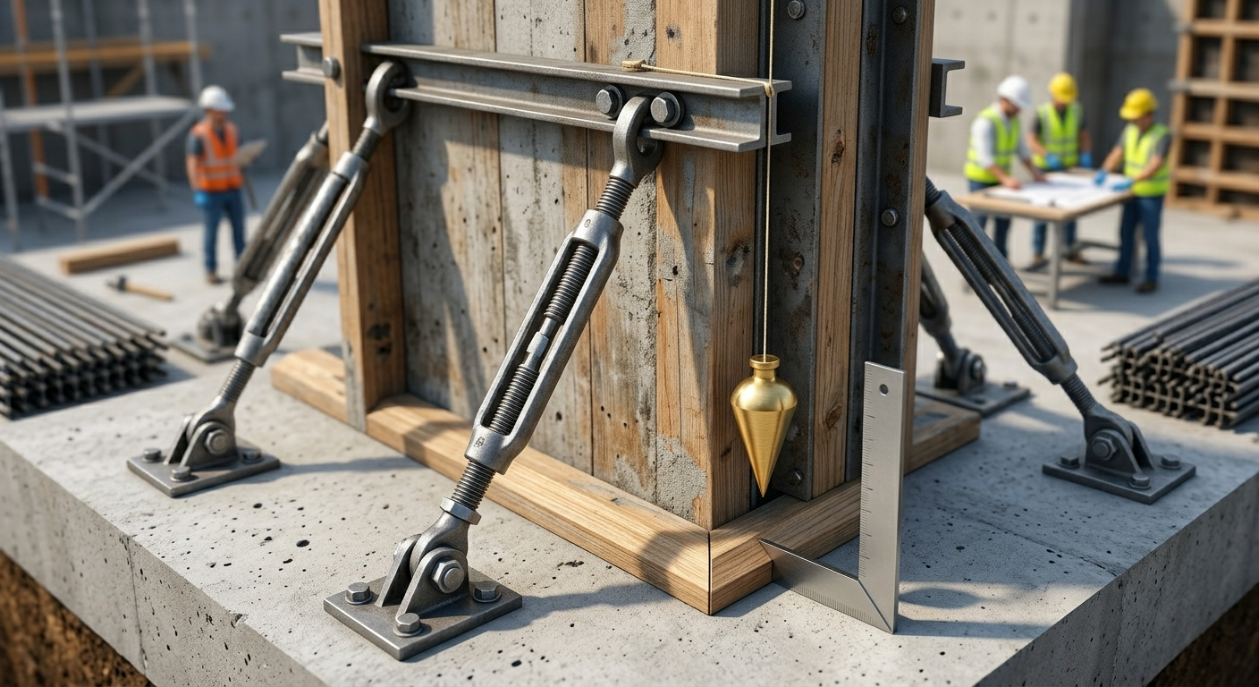
Strength & Stability: The formwork must be extremely strong, stable, and rigid. It has to hold the heavy load of wet, fresh concrete during the pour without shifting or changing shape.
-
Positioning: Position the formwork and shuttering to the exact correct lines. It must be perfectly plumb (straight up and down) and level, matching the shape, lines, elevations, and dimensions shown on the IFC drawings.
-
Surface Quality: The inner faces of the forms must be truly flat. There should be no undulations (waves) or corrugations that could ruin the final look of the finished concrete.
-
Chamfer Strips: Use 20 mm chamfer strips (or as approved) on all exposed edges, exactly as shown on the IFC drawings.
-
Bracing: Support and brace all forms adequately. They must hold their exact position during and after the concrete pour. They must be built tight enough to prevent any mortar leakage. (Leaking mortar leads to honeycomb concrete!)
Pre-Pour Preparations
-
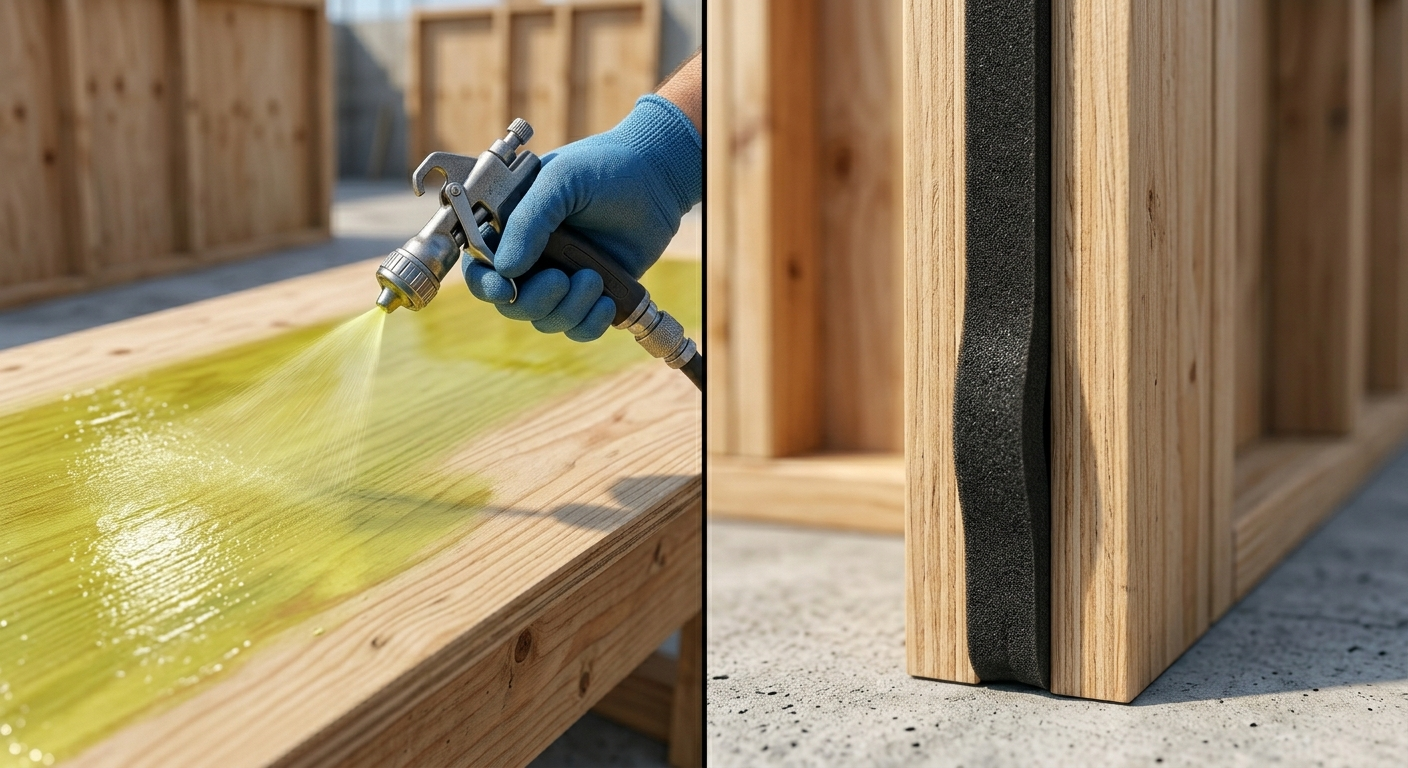
Release Agent: Before placing any steel reinforcement, thoroughly clean the form surfaces and coat them with an approved form release agent (shuttering oil).
-
⚠️ Crucial Safety Note: Do not spray release agent after the rebar is installed. If oil gets on the rebar, the concrete will not bond to the steel!
-
-
Sealing Joints: Fix foam tape to all formwork joints and edges. This prevents the loss of cement slurry during vibration.
-
Embedments: Accurately position the forms to the correct tolerances. Firmly secure all anchors, bolts, inserts, supports, hangers, pipe sleeves, drains, and water stoppers before any concrete is poured.
Stripping & Removal

-
Removal Timing: Only remove the forms strictly according to the project specifications and requirements.
-
Safe Handling: Do not throw form sheets down to the ground. Take extreme care so you do not damage the formwork materials. (Dropping forms is a massive struck-by hazard for anyone walking below).
-
Maintenance: After carefully removing the form sheets, take them to the site workshop for minor repairs and oiling.
-
Storage: Segregate the form sheets properly by size and store them under a shelter so they are ready for the next use.
Quality & Approvals
-
Submit a request for final checking and approval to the Customer/Consultant as required by the project.
-
Non-Conformity: If something fails inspection at any stage, the segregated items must be covered by a method statement. A Corrective Action Request (CAR) will be raised following the client’s official procedure.
Addendum: Associated Excavation Works
(Note: As per project file PE-317/MOS-CVL-13 incorporated into this package, the following rules apply when formwork involves foundational excavation).
Additional Excavation Responsibilities:
-
QA/QC Engineer: Checks excavation work as per approved ITP and IFC drawings.
-
Foremen: Directs execution of excavation works, controls personnel, and ensures proper tools/PPE are used in the trenches.
Excavation Tools & Equipment:
-
Backhoe (power excavator) – Note: Be aware of max. height clearance.
-
Pay load, Dump truck, Water truck.
-
Survey equipment, Drill machine.
-
Explosives & detonator (only for hard rock excavation).
-
Dozer with ripper, Front end loader, Wheelbarrow, shovel.
Excavation Procedure Highlights:
-
Layout: Survey the area and mark the excavation layout and slope cut stakes based on the IFC drawings.
-
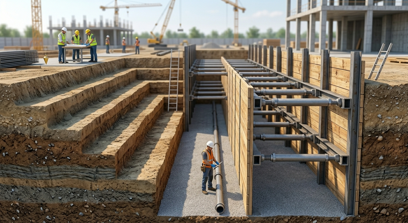
Working Space: Allow enough working space between the foundation being built and the edge of the excavation bottom. Personnel need room to install forms, bracing, and supports safely.
-
Measurements: Take all dimensions from the specific Bench mark/reference point for the site.
-
Depths: The ground level and depth of excavation shall be determined prior to work. Submit a request for a joint inspection of the Natural Surface Level (N.S.L) and area layout to the client/consultant.
-
Trench Safety (Critical): Ensure all safety requirements match the health and safety plan. Any excavation or trench over 1.2 Meters deep must have its sides sloped back to the natural angle of repose of the soil to prevent cave-ins. If space, adjacent structures, or ground conditions do not allow sloping, the sides must be shored (supported).
👷♂️ Make it sound like a real site engineer wrote it after 10+ years of experience: “I’ve seen too many guys try to rush the bracing or skip the foam tape just to get the pour started. Don’t do it. The pressure of wet concrete will find every weak point you left behind. Build it strong, check it twice, and never let anyone into an unshored trench over 1.2 meters. Let’s get to work and build this right.”
Be the first to comment