
What is a Formwork Method Statement?

A Formwork Method Statement is a formal, highly detailed engineering document that outlines the specific procedures, safety protocols, and quality controls required for the erection, inspection, and dismantling of temporary concrete molds on a construction site. It serves as the definitive operational guideline, ensuring that all shuttering activities conform to structural engineering blueprints, international standards like ACI 347R, and site-specific safety mandates.
The objective of this comprehensive method statement is to provide unambiguous, actionable guidelines for the erection and inspection of formwork at the site. This document universally covers the activities of formwork across all designated project sites, establishing a baseline for quality assurance, structural stability, and operational safety. By standardizing the approach to temporary structures, construction teams can systematically mitigate risks associated with concrete blowouts, dimensional inaccuracies, and workplace accidents.
Purpose and Operational Scope
The primary purpose of implementing a rigorous formwork method statement is to eliminate variability in construction execution. Concrete pouring introduces immense dynamic and static loads to temporary structures. If the formwork fails, the consequences range from expensive material rework to catastrophic structural collapse.
This method statement strictly governs the end-to-end lifecycle of shuttering works. It begins with the initial survey and setting out of the structure, progresses through the physical erection and bracing of the panels, dictates the precise application of chemical release agents, and concludes with the controlled stripping and subsequent material management of the formwork sheets. By adhering to this scope, project managers ensure that every concrete element—from deep foundation footings to high-rise vertical columns—is cast to the exact dimensions specified in the Issued for Construction (IFC) drawings.
Definitions and Standard Technical Abbreviations
Clear, standardized communication is the bedrock of successful construction management. Misinterpreting a technical acronym on-site can lead to critical engineering errors. The following definitions and abbreviations are universally adopted within this method statement to ensure total clarity among all project stakeholders.
| Abbreviation | Technical Definition | Operational Context |
| IFC | Issued for Construction Drawings | The final, approved architectural and structural blueprints that site engineers must follow. Formwork cannot be erected based on preliminary or tender drawings. |
| ITP | Inspection Test Plan |
A structured document detailing every required quality check, the specific testing methodology, and the designated personnel responsible for approval before concrete pouring begins. |
| CAR | Corrective Action Request | A formal procedure initiated when an inspection reveals non-conformity in the formwork. The CAR dictates the steps required to rectify the defect and prevent recurrence. |
| Panel Form | Reusable Formwork Element |
Engineered modular forms designed to withstand multiple pouring cycles without structural degradation. |
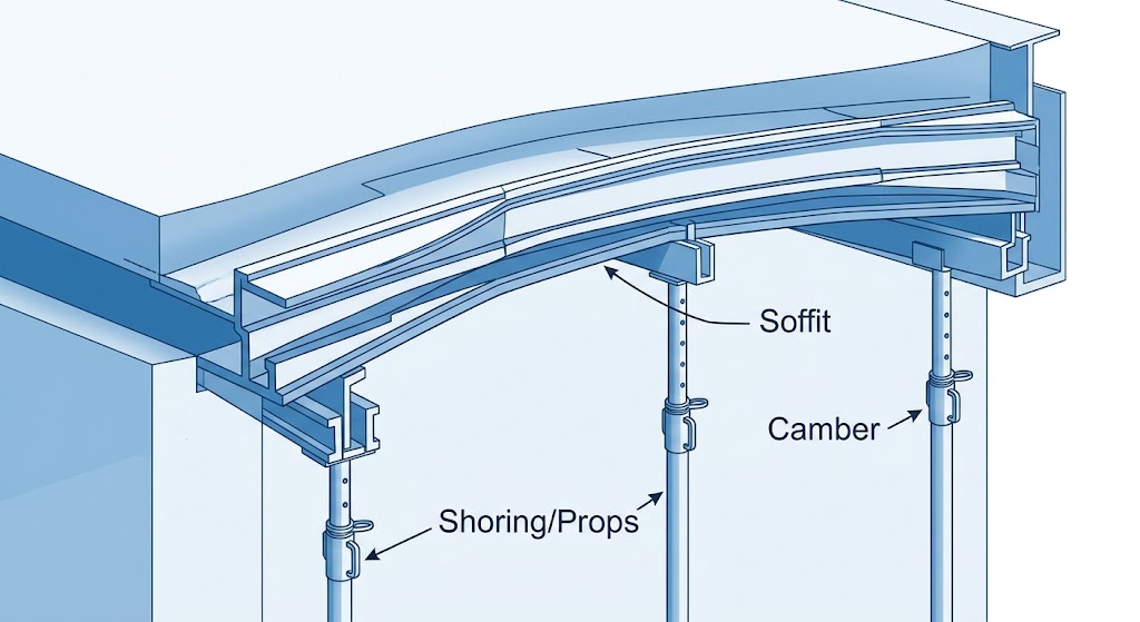
| Soffit | Horizontal Shuttering |
The formwork placed directly beneath horizontal structural elements, such as suspended slabs or concrete beams. |
| Camber | Calculated Upward Curvature |
A deliberate, slight upward shape given to horizontal formwork members to counteract the inevitable downward deflection caused by the weight of wet concrete. |
| Propping/Shoring | Vertical Support Systems |
The installation of load-bearing vertical struts or scaffolding designed to transfer the weight of horizontal formwork safely to the ground or lower floors. |
Key References and Structural Standards
Formwork execution does not occur in a regulatory vacuum. This method statement is strictly governed by a hierarchy of construction drawings, project technical specifications (PTS), and internationally recognized engineering standards.
ACI 347R: Guide to Formwork for Concrete

The primary structural reference governing the material selection and engineering of the temporary structures is ACI 347R (American Concrete Institute Guide to Formwork for Concrete). This globally recognized standard dictates the necessary calculations for formwork pressure, the allowable deflection tolerances, and the safety factors required for ties, braces, and supports. All formwork materials—whether engineered wood, fabricated steel, or driven sheet piling—must strictly confirm to the specifications outlined in ACI 347R to ensure they can withstand the anticipated hydrostatic pressure of fresh concrete.
Local Building Codes and Safety Regulations
In addition to international guidelines, formwork operations must align with local jurisdictional mandates. For example, projects operating under the Building Code of Pakistan (BCP-2021) must ensure that temporary falsework can withstand seismic lateral forces expected in the specific geographic zone.
Furthermore, local development authorities often dictate spatial and logistical constraints. The Lahore Development Authority (LDA) Building Bylaws, for instance, strictly regulate ground coverage, setback boundaries, and clear storey heights. Formwork must be designed so that its exterior bracing and scaffolding do not encroach into mandatory setback zones. Additionally, safety regulations, such as the Punjab Community Safety Act, mandate that formwork storage areas be equipped with accessible, functional fire extinguishers due to the high flammability of dry timber forms and chemical release agents.
Hierarchical Responsibilities in Formwork Operations

A successful concrete pour requires a highly coordinated chain of command. Every individual on the construction site, from the overarching project manager to the operatives handling the physical materials, carries specific, non-delegable responsibilities regarding formwork execution and safety.
Project and Construction Manager
The Project/Construction Manager sits at the apex of the site hierarchy. This role is accountable for the overall implementation and monitoring of all activities detailed within this method statement. They ensure that adequate resources, including manpower, specialized tools, and engineered materials, are allocated to the formwork phase. Their oversight guarantees that the project schedule aligns with the necessary curing times required before stripping can safely occur.
Site Manager
The Site Manager serves as the primary operational authority on the ground. Their responsibilities are comprehensive and encompass four main pillars:
-
Over-all Direction: Translating the project schedule into daily operational targets for the formwork gangs.
-
Monitoring: Continuously observing the progress and structural integrity of the formwork assembly.
-
Coordination: Managing the interface between the formwork carpenters, the steel reinforcement (rebar) teams, and the concrete supply logistics.
-
Control: Exercising authority over all construction activities related to formwork and shuttering, including the power to halt work if unsafe conditions arise.
Site Engineer
The Site Engineer acts as the critical link between the theoretical design and physical execution. They are directly involved in the granular planning and physical execution of the formwork and shuttering works. The Site Engineer must translate the IFC drawings into actionable instructions for the foremen. They calculate the precise spacing of vertical props, ensure the correct alignment of the formwork faces, and verify that the specified camber is accurately applied to horizontal slab soffits to prevent post-pour sagging.
QA/QC Engineer (Quality Assurance / Quality Control)
Quality control is an independent function designed to protect the structural integrity of the final product. The QA/QC Engineer operates with specific mandates:
-
Monitoring Tests: They execute all inspections dictated by the approved Inspection Test Plan (ITP). This includes verifying dimensions, plumbness, and the tightness of joints before concrete is authorized for pouring.
-
Laboratory Coordination: They coordinate directly with independent testing laboratories. This ensures that concrete sample cubes are properly cast during the pour and tested for compressive strength, providing the scientific data required to authorize the eventual stripping of the formwork.
-
Drawing Verification: They cross-reference the physical formwork assembly strictly against the approved ITP and the IFC drawings, ensuring zero deviation from the architectural intent.
Foremen
Foremen are the seasoned supervisors managing the labor force directly. Their responsibilities are highly tactile and immediate:
-
Direct Execution: They oversee the hands-on assembly of the formwork and shuttering, ensuring that the physical labor aligns exactly with the engineered plans.
-
Instruction and Control: They directly control the working personnel, providing continuous, real-time instruction on cutting, assembling, and bracing the forms.
-
Safety and Housekeeping: Foremen must ensure that all works are performed using the proper tools and equipment. They enforce the mandatory use of Personal Protective Equipment (PPE) and maintain rigorous housekeeping around the working area to prevent trip hazards and material degradation.
HSE Engineer / Supervisor (Health, Safety, and Environment)
Formwork erection involves significant hazards, including working at heights, manual handling of heavy materials, and the use of power tools. The HSE Engineer is responsible for mitigating these risks:
-
Plan Review: They meticulously review the Safe Work Plan (SWP) prior to the commencement of any physical work.
-
Permit Management: They issue and monitor specific work permits, ensuring that activities like high-elevation scaffolding erection or heavy crane lifts are properly risk-assessed.
-
Continuous Observation: If the project requires specific safety submittals to the client or consultant, the HSE Supervisor ensures these are implemented and continuously observed during the subsequent steel rebar and reinforcement phases.
Essential Tools, Equipment, and Plant
The precision and safety of formwork erection depend heavily on the quality and appropriateness of the tools utilized. Using incorrect or compromised tools leads to dimensional inaccuracies, grout leakage, and severe safety hazards. The following specialized tools are mandatory for the execution of this method statement.
| Tool / Equipment | Primary Operational Function |
| Cutting Disc / Circular Saw | Utilized for the high-precision sizing of plywood sheets and timber bracing. Exact cuts are vital to ensure formwork joints sit flush, preventing the leakage of cement slurry. |
| Jacksaw (Hand Saw) | Employed for detailed, manual modifications where power tools cannot safely reach, or for delicate trimming of timber components around complex architectural features. |
| Hammer / Striker | The primary hand tool for the physical assembly of timber formwork, driving nails to secure joints and structural bracing elements. |
| Pin / Nail Puller (Pry Bar) | Essential for the safe dismantling and stripping of formwork. It allows carpenters to remove fasteners without inflicting severe mechanical damage to the reusable form sheets. |
| Measuring & Survey Tools |
Plumb bobs, spirit levels, and laser alignment tools are critical. Formwork must be perfectly vertical (plumb) and horizontal (level) to ensure the final concrete structure meets engineered tolerances. |
While heavy earthmoving plant machinery—such as backhoes, dozers with rippers, and front-end loaders—are critical for the initial site survey, excavation, and foundational layout, the actual erection of formwork relies primarily on the precision hand tools and power equipment listed above.
Pre-Erection Engineering and Site Preparation
The physical assembly of formwork is preceded by meticulous engineering and site preparation. A failure in this preliminary phase cascades into massive structural errors during the concrete pour.
Consultation of IFC Drawings and Shop Drawings
The process begins with an exhaustive review of the Issued for Construction (IFC) drawings. Site engineers must consult these documents carefully to understand the exact shape, size, dimension, and support assembly required. The structural drawings dictate the thickness of the concrete cover, the positioning of internal steel reinforcement, and the location of critical load-bearing nodes.
From the IFC blueprints, detailed shop drawings must be prepared specifically for the formwork and shuttering. These shop drawings translate the architectural design into a practical assembly guide for the carpenters. They explicitly detail the layout of the formwork panels, the positioning of scaffolding pipes, the locations of joints, and the arrangement of shuttering plates. By planning the sizes, quantities, and types of formwork in advance, the project engineer prevents ad-hoc, uncontrolled modifications on the site.
Setting Out and Foundation Preparation
Before formwork can be placed, the ground or foundational base must be thoroughly prepared. The area is surveyed, and exact boundary lines and elevations are marked using precision leveling instruments. If the formwork is to be erected on soil, the ground must be rigorously compacted, and base plates or timber sleepers must be laid down to ensure the vertical props do not sink under the extreme weight of the wet concrete. When forms are being attached to previously cast concrete walls or slabs, the existing surface must be cleaned and inspected to ensure a flush, secure connection.
Formwork Erection Procedure and Structural Controls
The erection phase is the most critical component of the method statement. Formwork is not merely a geometric mold; it is a temporary, highly stressed load-bearing structure.
Structural Rigidity and Material Selection
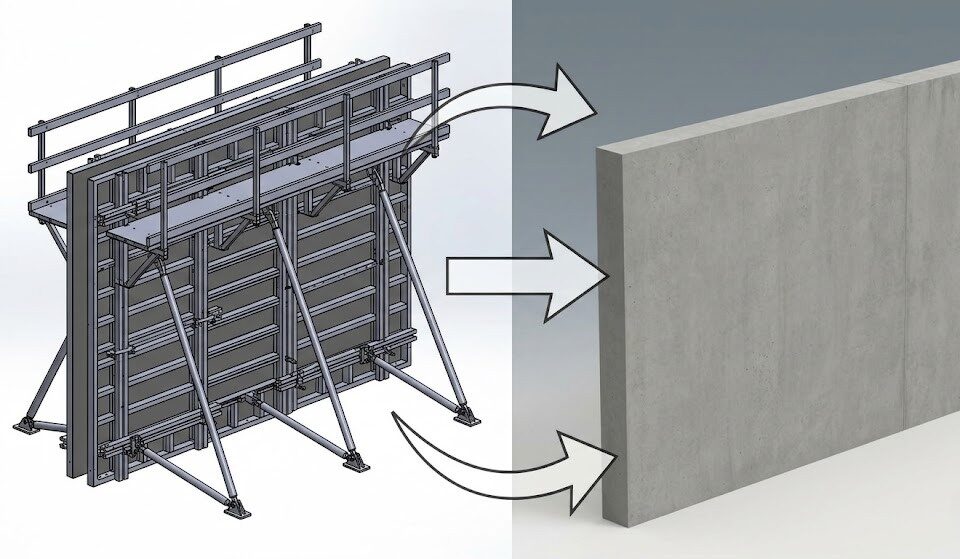
All formwork materials utilized on-site must strictly conform to ACI 347R standards. Whether the project specifies engineered wood, high-tensile steel, or driven sheet piling, the type, size, shape, and quality of the materials must be consistent with the specified architectural finishes.
The primary mandate is that the formwork shall be inherently strong, completely stable, and sufficiently rigid to withstand the immense dynamic load of fresh concrete pouring. Wet concrete exerts extreme hydrostatic pressure outward against the vertical forms, similar to water in a tank. The formwork must maintain its exact position and shape throughout the violent vibration process used to consolidate the concrete and remove trapped air pockets.
Positioning, Alignment, and Plumbness
Shuttering must be positioned to absolutely correct lines. It must be perfectly plumb (vertically straight) and level (horizontally flat), conforming entirely to the shape, lines, elevations, and dimensions depicted on the IFC drawings. Site engineers utilize high-precision laser levels and traditional plumb bobs to continuously verify this alignment during the erection process. Any deviation from plumbness results in eccentric loading on the final concrete column or wall, which drastically reduces the building’s overall structural capacity.
Surface Quality and Joint Sealing
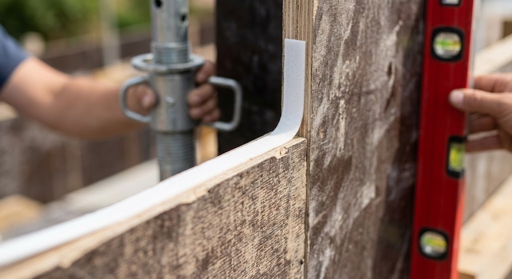
The physical faces of the forms that will make contact with the concrete must be true, flat, and entirely free from any undulation or corrugation. Imperfections in the plywood or steel facing will mirror exactly onto the finished concrete surface, leading to costly cosmetic repairs or structural rejection.
To prevent the loss of cement slurry—a critical failure known as grout leakage—foam tape must be meticulously fixed to all formwork joints, edges, and abutting surfaces. When grout leaks through a poorly sealed joint, it leaves behind a segregated mix of coarse aggregate, creating weak, porous “honeycomb” pockets in the concrete structure that severely compromise its strength.
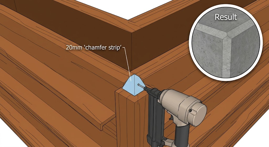
Implementation of Chamfer Strips

A specific architectural and structural requirement is the mandatory use of 20 mm chamfer strips. These triangular strips of wood or plastic must be securely nailed or glued into all exposed internal corners and edges of the formwork. The chamfer strip serves two vital purposes:
-
Aesthetic and Safety: It creates a smooth, beveled edge on the final concrete structure, eliminating sharp 90-degree corners that are prone to chipping and present a safety hazard to occupants.
-
Stress Relief: In structural engineering, sharp internal corners create stress concentrations. A chamfered edge distributes these forces more evenly, significantly improving the durability of the concrete element over its lifespan.
Support, Bracing, and Tolerance
Once the primary panels are aligned, all forms must be adequately supported and braced. This involves installing horizontal walers, vertical soldiers, and diagonal steel tie-rods. The support system must be engineered to maintain the desired position not only during the violent pouring of the concrete but also as the concrete cures and begins to shrink. The system must be built sufficiently tight to prevent any mortar leakage under pressure. All forms must be positioned accurately to specified tolerances, and the carpenters must firmly secure all internal anchors, bolts, inserts, supports, hangers, pipe sleeves, drains, and water stoppers before any concrete is poured.
Concrete Release Agents: Chemical Application and Best Practices
A critical, yet frequently mishandled, step in the formwork process is the application of concrete release agents. Before any steel reinforcement (rebar) is placed inside the mold, the interior surfaces of the forms must be thoroughly cleaned and coated with an approved release agent.
The Mechanism of Release Agents
Concrete is highly adhesive when wet. If poured directly against untreated timber or steel, the cement matrix will bond permanently with the formwork surface. A release agent acts as a chemical or physical barrier, ensuring that the formwork can be stripped away smoothly without tearing the surface off the newly cured concrete.
There are several types of release agents:
-
Vegetable Oil-Based: Highly recommended due to their biodegradable, environmentally friendly nature. They provide an excellent surface finish and pose minimal health risks to the application team.
-
Water-Based Emulsions: Cost-effective and non-flammable, though they require specific drying times for the water to evaporate before pouring.
-
Chemically Reactive Agents: These contain active compounds that react slightly with the alkaline cement to create a microscopic, soapy film at the interface, guaranteeing a flawless release for high-end architectural concrete.
Application Best Practices
The golden rule for applying form release agents is “less is more.” Applying an excessively heavy coat is not only wasteful but actively detrimental to the concrete. Excess oil will pool in the corners and low spots of the formwork. When concrete is poured over these pools, the chemical retards the hydration process, resulting in localized soft spots, dark discoloration, and severe surface pitting known as “bugholes”.
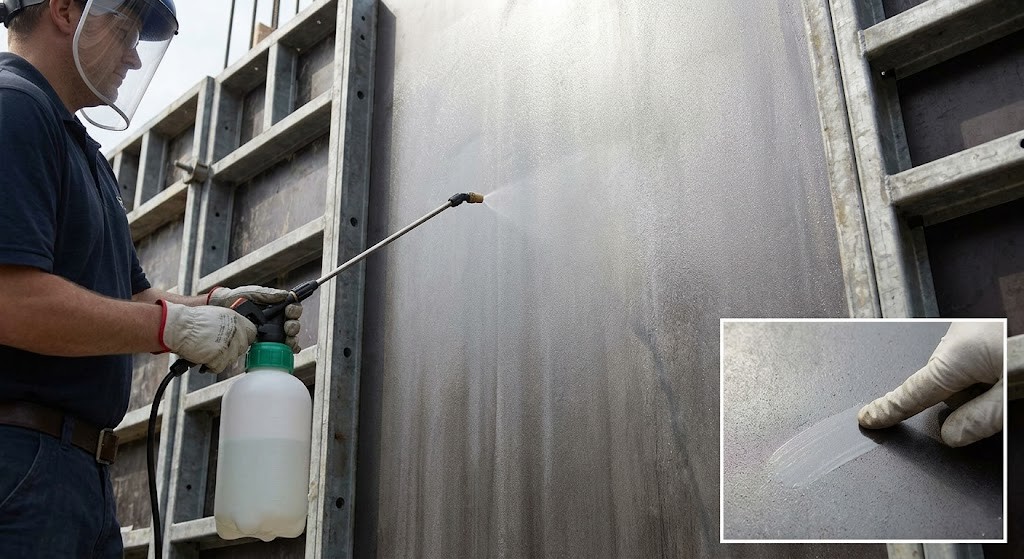
Application should be carried out using an oil-resistant pump sprayer fitted with a stainless-steel flat spray nozzle, pressurized to roughly 4 to 6 bar. This ensures a highly atomized, thin, and perfectly uniform film across large panels. For intricate details, corners, and chamfer strips, high-quality brushes or rollers should be utilized.
Site inspectors verify the correct application thickness using a simple “finger test.” When a finger is swiped across the treated formwork, the surface should feel slick but not wet. If liquid accumulates and clear tracks are left in a thick oil film, the formwork has been oversprayed and must be wiped down with rags before any rebar is installed. Crucially, if the release agent inadvertently coats the steel reinforcement, it must be meticulously cleaned off immediately, as the oil will destroy the vital structural bond between the steel rebar and the concrete.
Concrete Placement and Structural Monitoring
With the formwork fully erected, braced, and chemically treated, the operational focus shifts to the concrete placement phase. This is a period of maximum stress for the temporary structures.
The concrete gang must prepare the site in advance, staging screed units, high-frequency immersion vibrators, and ensuring all operatives are wearing proper PPE, including heavy-duty rubber gloves, safety glasses, and impermeable boots. For significant pours, such as high retaining walls or deep columns, the concrete is delivered via boom pumps.
The concrete must be placed systematically in horizontal layers, typically 300 mm to 500 mm thick. Dumping massive volumes of concrete into a single spot dramatically spikes the localized hydrostatic pressure, which can easily blow out the formwork panels. As each layer is placed, operatives use vibrators to consolidate the mix and drive out entrapped air.
During this high-stress operation, a dedicated team of carpenters must continuously patrol the exterior of the formwork. They monitor the structural integrity of the props, braces, and tie-rods. Any sudden bowing of the plywood, slipping of wedges, or the sudden appearance of cement slurry leaking from a joint indicates an imminent failure. If these warning signs occur, the concrete pour must be immediately halted by the Site Manager until the formwork can be emergency-braced and secured.
Formwork Removal (Stripping) and Material Management
The removal of formwork, technically referred to as “stripping,” is a hazardous operation that requires precise timing and strict adherence to structural engineering guidelines. Formwork cannot simply be dismantled when it appears dry; it must only be removed as per the exact project specifications and engineering requirements.
Calculating the Stripping Time
Under no circumstances can the load-bearing formwork system be removed until the concrete has achieved a predetermined compressive strength. This threshold is typically defined as the point where the concrete reaches at least twice the stress level it will be subjected to at the exact time of removal.
The curing rate is heavily dependent on the ambient air temperature, humidity, and the specific chemical mix of the cement. To accurately determine this, the QA/QC Engineer coordinates the crushing of concrete test cubes that were cast during the pour and cured under identical environmental conditions. Only when the independent laboratory confirms that the necessary strength threshold (e.g., a minimum of 5 N/mm² for vertical forms) has been reached can the Site Manager authorize the stripping sequence.
The Sequence of Disassembly
The method of disassembly is dictated by the principles of load distribution. All components of the formwork system must be loosened and removed gradually and carefully. A sudden release of formwork can transfer massive shock loads onto the “green” (newly cured) concrete, causing micro-fractures.
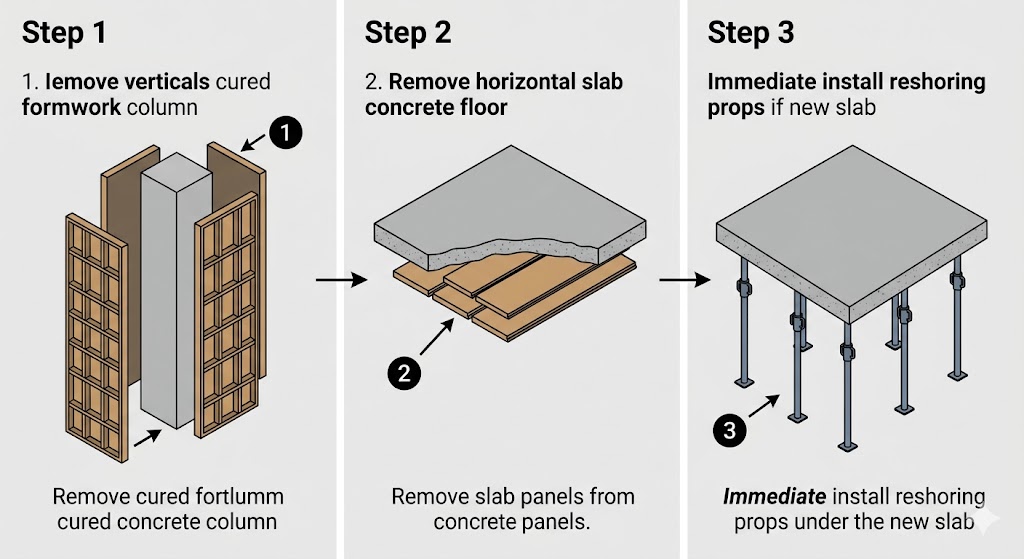
-
Vertical Faces (Non-Load Bearing): The shuttering forming the vertical faces of walls, beams, and column sides is removed first. Because these panels do not bear vertical loads and solely retain the lateral pressure of the wet concrete, they are safe to remove early in the curing process.
-
Slab Soffits (Light Load Bearing): The shuttering forming the soffit (underside) of floor slabs is removed next. However, as the slab cannot yet support its full design weight, extensive reshoring (temporary vertical props) must be immediately re-installed beneath the slab to support it during the remainder of the curing cycle.
-
Heavy Load Soffits: The formwork forming the soffit of heavy main beams, deep girders, or other heavily loaded structural members must be removed absolutely last, as these elements require the longest curing time to achieve self-supporting strength.
Material Handling and Post-Stripping Protocol
A critical directive of this method statement is that form sheets shall not be thrown down to the ground. Tossing panels from height shatters the engineered plywood faces, warps aluminum frames, and bends steel locking pins, rendering expensive materials useless for the next pour. Extreme care must be taken to lower the panels safely using ropes or cranes, taking great care so as not to damage the formwork or the newly exposed concrete surface.
After careful removal, the form sheets must be transported immediately to the designated site workshop. Here, they undergo thorough cleaning to remove any residual concrete scale. They receive minor repairs, such as patching small holes or replacing damaged chamfer strips, and are re-oiled for preservation. Finally, the sheets are properly segregated according to their specific size and modular type, and stored neatly under weather-proof shelter for onward usage.
Upon completion of the stripping and clean-up, the Site Engineer submits a formal request for final checking and approval by the Client or Consultant. If the final concrete structure displays defects—such as severe honeycombing, dimensional misalignment, or structural spalling—a Corrective Action Request (CAR) shall be officially raised. The defective work must be documented, and a formal remediation procedure must be approved before the project can proceed to the next phase.
Comprehensive Inspection and Quality Assurance Checklists

Quality assurance is not a final step; it is a continuous process integrated into every phase of the method statement. The Inspection Test Plan (ITP) dictates the specific checks that the QA/QC Engineer must physically sign off on. The following checklist details the mandatory verification points required before any concrete pour is authorized.
| Inspection Category | Specific Verification Points | Reference / Tool |
| Design & Documentation |
Verify that the shop drawing is fully detailed and has been formally approved by a competent structural engineer. |
IFC Blueprints / ITP Document |
| Material Integrity |
Inspect all reusable panels for surface wear, warping, or delamination. Reject any damaged materials. |
Visual Inspection |
| Alignment & Plumbness |
Check all formwork panels for absolute vertical and horizontal alignment. Ensure dimensions exactly match drawings. |
Laser Level / Theodolite |
| Joint Sealing |
Verify that foam tape is correctly applied to all joints and that there are no visible gaps where grout could leak. |
Visual / Physical Check |
| Support & Bracing |
Inspect the spacing, tightness, and footing of all vertical props and diagonal braces. Ensure resting on firm, uniform foundations. |
Torque Wrench / Spirit Level |
| Release Agent |
Confirm that release agents are applied uniformly in a thin film, with no pooling, and that no overspray has contaminated the rebar. |
Finger Test / Visual |
| Reinforcement (Rebar) |
Verify rebar size, spacing, secure tying, and that the specified concrete cover depth is maintained using appropriate spacers. |
Measuring Tape / IFC Plans |
Internal Linking Strategy for Construction Websites
In the digital era, demonstrating technical expertise through high-quality documentation is a powerful mechanism for building brand authority and generating organic search traffic. For construction firms, engineering consultancies, and building material suppliers, a strategic internal linking architecture is essential to maximize the SEO value of complex technical guides like this Formwork Method Statement.
Building Topical Authority via Hub-and-Spoke Architecture
Search engines reward websites that demonstrate deep, structured expertise on specific subjects. A highly effective SEO strategy involves creating a “Pillar Page” (the hub) that provides a broad overview of a major topic—such as “Complete Guide to Structural Concrete Construction.”
From this pillar page, internal links should branch out (like spokes) to highly detailed, specific articles, such as this guide on Formwork Erection, another guide on “Steel Reinforcement Tying Techniques,” and a third on “Concrete Curing Methodologies”. This clustered structure signals to search engine crawlers that the website holds comprehensive topical authority over the entire lifecycle of concrete construction.
Strategic Anchor Text and User Journey Navigation
When inserting internal links, the use of descriptive anchor text is critical. Avoid generic, non-descriptive phrases like “click here for more.” Instead, utilize exact match or partial match semantic keywords that clearly define the destination page. For example, a link within a paragraph discussing safety should read: “review our comprehensive construction site fall protection guidelines.” This precise language helps search algorithms map the exact relevance of the connected pages.
Furthermore, internal links must align logically with the user’s search journey. If a reader is studying the “Concrete Release Agents” section of this method statement, an internal link pointing to a product page for “Water-Based Emulsion Sprayers” or an article on “Troubleshooting Concrete Surface Defects” provides immediate, highly relevant value. This keeps the user engaged, drastically increases the time spent on the site, and significantly lowers the bounce rate—all critical metrics for achieving first-page Google rankings.
Regular technical audits must be conducted to ensure this web of links remains robust. Broken links that lead to 404 error pages create frustrating dead-ends for both human readers and search engine crawlers, wasting valuable “crawl budget” and diluting the site’s overall SEO power.
Frequently Asked Questions (People Also Ask)
What is the purpose of chamfer strips in formwork?
Chamfer strips, typically 20 mm in size, are installed in the internal corners of formwork to create a beveled edge on the finished concrete. This prevents sharp 90-degree corners from chipping or spalling during the building’s lifespan and eliminates localized stress concentrations in the structural element.
Why is foam tape used on formwork joints?
Foam tape is applied tightly to all joints and abutting edges of the formwork to create a watertight seal. This crucial step prevents the leakage of cement slurry (grout) under the intense hydrostatic pressure of the wet concrete. Preventing grout loss ensures the final concrete remains dense and free from weak, porous honeycomb defects.
How do you test if too much release agent has been applied?
Site engineers utilize a simple “finger test.” When you swipe a finger across the chemically treated formwork panel, the surface should feel slick, leaving a thin, glossy film. If the release agent pools or leaves distinct, wet tracks indicating a thick layer, it has been over-applied. Excess agent must be wiped off, as it will retard the concrete’s curing process and cause surface defects like bugholes.
Why must vertical formwork be removed before horizontal slab soffits?
Vertical formwork (used for walls and columns) only retains the lateral hydrostatic pressure of wet concrete. Once the concrete sets, it bears its own vertical load, allowing the side panels to be safely stripped. Conversely, horizontal soffits (underneath slabs and beams) bear the massive gravitational dead weight of the concrete. They must remain in place significantly longer—often requiring extensive reshoring—until the slab achieves the compressive strength necessary to support itself.
What is an ITP in construction formwork?
An ITP (Inspection Test Plan) is a formal quality assurance document that lists every specific inspection, dimensional check, and material verification required during the formwork process. It designates exactly who (e.g., the QA/QC Engineer) is responsible for signing off on each specific quality checkpoint before the final authorization to pour concrete is granted.
Conclusion
The successful execution of structural concrete operations relies entirely on the discipline, precision, and rigorous adherence to engineering standards outlined within the Formwork Method Statement. Formwork is far more than a simple mold; it is a highly stressed temporary structure that dictates the ultimate dimensional accuracy, surface quality, and structural integrity of the final building.
By meticulously controlling every phase of the operation—from the initial consultation of IFC drawings to the precise application of release agents, the rigorous bracing against hydrostatic pressure, and the carefully timed, sequenced stripping of the panels—construction teams can systematically eliminate the risks of structural failure. Furthermore, by embedding specific quality assurance checks (ITP) and immediate corrective actions (CAR) into the daily workflow, project managers ensure that safety and architectural fidelity remain uncompromised. Ultimately, a strictly enforced method statement protects not only the vast economic investment in building materials but, most importantly, the lives and safety of the personnel operating on the construction site.
Be the first to comment