
If you are managing a construction site, you know that pouring concrete is a high-stakes operation. It involves heavy machinery, deep excavations, strict timelines, and immense physical pressure. To control this chaos safely, you need a solid concrete method statement.
From an Environmental, Health, and Safety (EHS) perspective, this document is your ultimate playbook to ensure every worker goes home safe and the structure stands the test of time. For more general safety foundations, check out our comprehensive workplace safety guidelines.
1. Purpose & Scope of the Concrete Method Statement
The objective of this concrete method statement is to provide general guidelines for the erection and inspection of formwork and concrete operations at the site. Furthermore, it outlines the critical preparatory groundworks and excavation steps required to ensure a stable foundation for all structural support systems.
Working with wet concrete, heavy steel props, and deep excavations involves significant safety challenges. A collapse can result in concrete blowouts, massive financial losses, and severe injuries. This method statement guarantees that every worker, supervisor, and engineer understands the exact sequence of work to execute the pour flawlessly and safely.
2. Definition & Abbreviation
Clear communication on a construction site prevents accidents.
Project Specific Abbreviations:
-
IFC: Issued for Construction drawings. (The final, stamped blueprints).
-
ITP: Inspection Test Plan. (A mandatory checklist of tests passed before the next stage begins).
-
CAR: Corrective Action Request. (A formal document raised when work fails quality/safety standards).
General Construction and Technical Terms:
-
Aggregate: Coarse materials like sand and gravel mixed with cement.
-
Backfill: Putting soil back into an excavated area to restore ground level.
-
Props / Shoring: Heavy vertical steel posts holding formwork up.
-
Shuttering: Flat panels (plywood/steel) that touch the wet concrete to shape it.
3. References & External Standards
All work must comply with established engineering guidelines. The site team must refer to:
-
Construction drawing: Approved blueprints showing exact measurements.
-
PTS: Project Technical Specifications dictating material quality and tolerances.
-
American Concrete Institute (ACI) 347 R: Guide to formwork for concrete. The international standard calculating how much pressure wood/steel can handle before breaking.
4. Responsibilities in the Concrete Method Statement
Building a culture of safety means everyone communicates clearly across all trades. Your Concrete Method Statement should outline the following roles:
-
Project/Construction Manager: Overall implementation and monitoring. Provides budget and personnel to execute the job safely.
-
Site Engineer: Prepares shop drawings, establishes the safe work plan, and applies for mandatory work permits prior to commencement.
-
QA/QC Engineer: The independent voice of quality. Monitors tests (slump tests, cylinder samples) as per the ITP.
- HSE Engineer/Supervisor: Protects the workforce. Enforces the capping of exposed rebar, fall arrest systems, and strict PPE compliance as part of your broader industrial safety protocols.
5. Tools & Equipments
Using damaged or worn elements reduces reliability. Equipment must be proactively inspected daily.
-
Hand & Power Tools: Cutting discs, Jacksaw/Circular Saw (blade guards required), Hammers, and Pry bars for safe stripping.
-
Heavy Machinery: Backhoes, Pay loaders, Dump trucks (spotters mandatory), and Water trucks.
-
Surveying Tools: Total stations and laser scanners to ensure perfect horizontal and vertical formwork alignment.
6. Procedure: Ground Preparation and Excavation
Before formwork panels are erected, the earth must be meticulously prepared.
Step 1: Marking and Layout Survey the area and mark the layout. Provide allowance between the foundation and the trench wall so workers can safely swing a hammer.
Step 2: Trench Safety and Shoring Excavations over 1.2M deep must be sloped back to the natural repose of the soil to prevent cave-ins, strictly following OSHA trenching and excavation standards. Where sloping is impossible, sides must be heavily shored.

Safety Note: Barricade all reversing zones for heavy machinery and mandate trained spotters.
7. Procedure: Formwork Material Selection and Design
Step 1: Material Standards
Formwork material shall conform to ACI 347R. Cracked plywood or rusted steel frames must be rejected by the QA/QC team.
Step 2: Documentation and Shop Drawings
IFC drawings must be consulted to prepare formwork shop drawings, detailing exact assembly logic and scaffolding joints.
8. Procedure: Erection, Alignment, and Sealing
Step 1: Structural Integrity and Alignment
Formwork must be positioned plumb (vertical) and level (horizontal).
Step 2: Sealing and Bracing Against Pressure
Liquid concrete exerts massive sideways pressure. Fix foam tape to all formwork joints to prevent the loss of cement slurry, which causes severe structural defects known as “honeycombing.”
9. Procedure: Pre-Pour QA/QC Inspection
Before pouring, the system must be rigidly inspected via the ITP checklist:
| Inspection Category | Critical Checklist Items for the Site Engineer and QA/QC |
| Cleanliness | Shuttering material is completely clean. Rust and sawdust removed. |
| Alignment | Vertical and horizontal alignments are verified using a laser level. |
| Support Strength | Shuttering is properly fixed, braced, and capable of supporting mass. |
| Rebar Interface | Steel reinforcement is securely tied with adequate concrete cover. |
10. Procedure: Safe Concrete Pouring
During the pour, the formwork experiences maximum stress, and workers face severe chemical hazards.
-
Avoid Overloading: Do not dump large mounds of concrete in a single spot. Pour evenly in shallow layers.
-
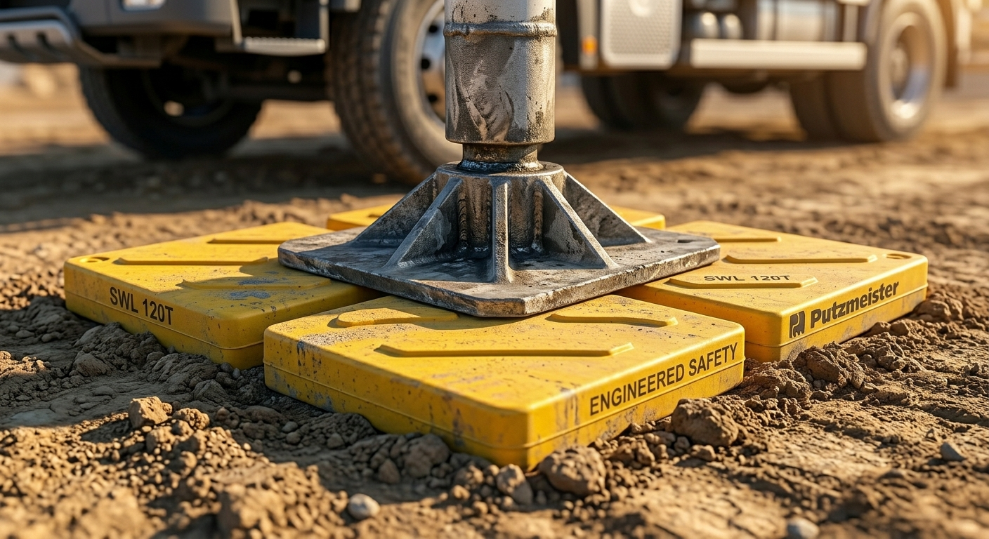
Ground Stability for Pumps: Concrete pump trucks must strictly use engineered outrigger pads.
-
Chemical Safety: Wet concrete is highly alkaline. Direct contact causes third-degree chemical burns.
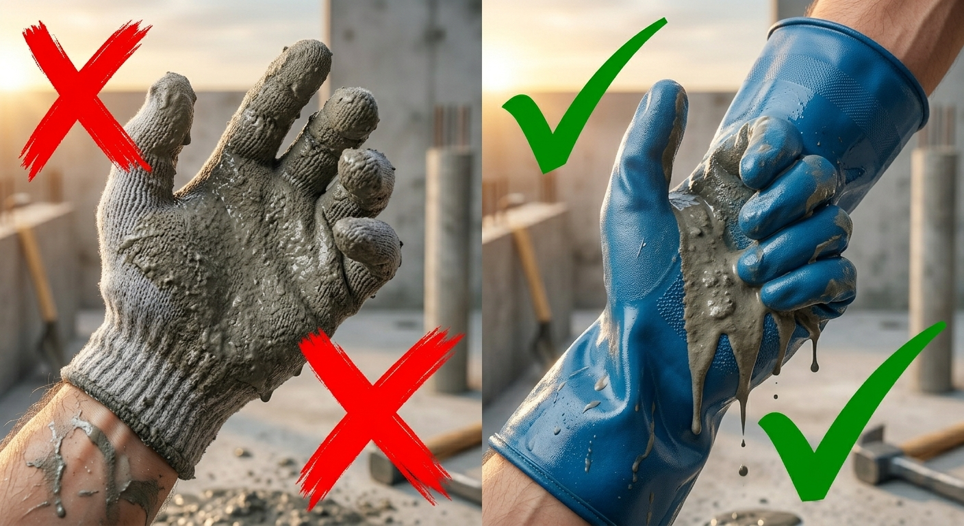
PPE Directive: Heavy-duty nitrile/rubber gauntlet gloves are non-negotiable.
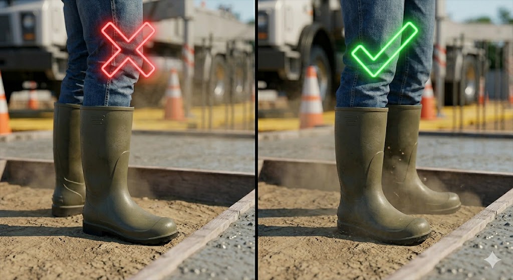
PPE Directive: Pants must go over the outside of rubber boots to prevent funnelling wet concrete against the skin.
11. Procedure: Formwork Stripping (Removal) and Storage
As dictated by your Concrete Method Statement, removing forms before the concrete has gained sufficient strength leads to disastrous consequences, including structural collapse.
Step 1: Authorization and Timing
The Site Engineer must verify concrete compressive strength through laboratory testing before stripping.
| Structural Element | Minimum Stripping Time | Why Wait? |
| Vertical Forms (Columns, Walls) | 16 to 24 hours | Forms do not hold weight; they only hold the shape. |
| Slab Soffit (Bottom of floors) | 3 days | Slabs must hold their own weight across a gap. |
| Beam Soffit (Bottom of beams) | 7 days | Beams support the heavy slabs above them. |
| Props to Slabs (under 4.5m wide) | 7 days | Props prevent the slab from sagging while it cures. |
| Props to Slabs (over 4.5m wide) | 14 days | Wide gaps create massive stress. Supports remain twice as long. |
Step 2: Safe Stripping Techniques
Barricade the drop zone. Wet the concrete to break the suction. Never throw loose panels down from heights (fatal struck-by hazard). Never climb partially stripped formwork.
Step 3: Reshoring and Back-Propping
Reshoring (placing vertical steel props back under the bare concrete slab) must be done immediately after stripping to support the slab against the weight of the construction work on the floor above.
Step 4: Cleanup, Storage, and Final Approval
Take form sheets to the site workshop for minor repairs/oiling. Segregate and store properly to minimize trip hazards. Request final checking from the Consultant. Raise a CAR for any non-conformity.
Be the first to comment